


The Flipper Nobody Respects: Designing a One-Tooth Partial Denture That Actually Seats

Every professional in digital dentistry eventually faces a moment of doubt: am I really designing this appliance, or am I just confirming what the software decided for me? That question sits at the heart of every removable case — and it is answered most honestly in the smallest one.
This article follows a seven-minute tutorial on designing a one-tooth partial denture, commonly called a flipper. We chose it deliberately. The flipper is often dismissed as a trivial case, something beginners practice on before "real" work. But strip away the simplicity and you find the complete anatomy of removable appliance thinking: define the boundary, respect the insertion path, control the undercuts, build the base, and let the fitting surface be decided by analysis — not guesswork.
This story speaks to the beginner who keeps postponing their first removable case, the designer who feels that removable appliance design is somehow "less than" fixed work, and the clinician who wants to understand what happens between the scan and the 3D printer. It is a reminder of the B4D philosophy at its quietest and clearest: technology should make you think better, not think for you.
— Dr. Samira Alrefaey
Blog Editor & Marketing Specialist | BlenderforDental

There is something quietly honest about a flipper. No pontic army. No framework to negotiate. One tooth, one socket, one decision about how the appliance will pass over the neighboring teeth. And yet, if you design it carelessly, the patient will feel it within the first hour — it will catch, rock, and refuse to seat. If you design it well, it disappears into their day.
That is the paradox this tutorial exposes. The case is small, but the thinking is complete. Every mistake you make here is a mistake you would make on a larger case — only here, the mistake is easier to see.
"A flipper is not a small design. It is a full removable appliance compressed into one tooth."
The whole workflow fits on one page, and the reasoning behind each stage holds the real value:

This article walks you through each stage step by step — not as a list of buttons to press, but as a chain of clinical reasoning. Each module in BlenderforDental makes one decision, and each decision sets up the next. Follow the reasoning, and the clicks become obvious.
The Problem Nobody Names: Appliances That Don't Know Which Way to Go
Before any software is opened, understand what the flipper has to survive. A removable appliance must be able to travel along one path — the path of insertion — from your hand into the patient's mouth, day after day. Any geometry that obstructs that path is an undercut. If the undercuts are left untouched, the appliance simply will not seat. If they are over-blocked, the appliance seats loosely and becomes a toy.
Most dental software handles this with automation: click "calculate," accept the blockout, print, and hope. The hope is the problem. When a black box decides your undercuts, you cannot defend the design, you cannot predict the fit, and you cannot learn from the failure. You become a passenger in your own workflow.

The B4D approach is different. You survey the model yourself. You decide the path of insertion. You set the undercut threshold with your own clinical judgment. The software does not design the appliance — you do, and it stays out of your way.
Step 1 — Wax Up: Define the Boundary Before You Remove Anything
The tutorial opens in the Wax Up module, and the first action is deliberate: draw a line around the cervical area of the tooth to be removed, then mark it as the gum line. Only then is an offset created to define the extraction socket.

And here is the reasoning behind it all in one view: the extracted tooth — now recolored light blue — seated back in the arch exactly where it began. From the same boundary that defined the socket, the design knows where the pontic belongs.

This order matters. The gum line is the boundary of the entire design — it determines where the appliance meets the tissue, where the pontic will sit, and where the fitting surface begins. Define the boundary first, and everything downstream inherits a clean reference. Define it second, and you spend the rest of the design patching it.
The tutorial's voice is careful here, and it is worth listening to:
"...the way that line is going to offset from the model."
Every point you place in that contact line is about to be offset into the socket definition, so draw around the contact with intention — the line is the seed of the whole case.
Then comes Section Tooth — the tooth is cut free from the arch at the gum line. Notice what you now hold in your hand: the exact tooth that will become the flipper's pontic. The extraction is not a deletion. It is a harvest.
One caution from the tutorial: keep the contact line clean and avoid letting it fold back on itself. A crossed or doubled line looks harmless on screen, but the offset algorithm inherits the error, and the socket geometry quietly breaks. This is the kind of mistake that costs you twenty minutes later, in a module you have already left.
Step 2 — Blockout: The Insertion Path Is a Decision, Not a Default
If the Wax Up module defined where the appliance lives, the Blockout module defines how it moves in and out. This is the step most designers rush — and it is the step that decides whether the printed flipper will seat.

The result of that care shows up where it counts: the contact areas. In the view below, the green blockout pads sit deliberately at the contacts — the extra clearance added by sculpting, before any appliance exists.
The workflow is a small ritual of analysis. First, the extracted tooth is recolored so the neighboring teeth stand out clearly — visibility is preparation, not decoration. The blockout layer is created with a default offset of 0.2mm, and the model is then surveyed to find the best path of insertion. The surveying sliders (X and Y) let you tilt the virtual survey line until the path runs cleanly across the mesial aspects of the adjacent teeth and through the contact areas. Undercuts are marked and displayed on screen, so you see exactly what the appliance will collide with.
Then comes the moment that separates thoughtful design from default-clicking. The tutorial explicitly warns against accepting the auto-default models when undercuts are deep. The default undercut threshold sits at -0.4mm — and if you leave it there on a case with pronounced undercuts, the blockout will be so aggressive that the physical appliance becomes too tight. The patient will not be able to insert or remove it. The tutorial's designer moves the slider manually, from -0.4 to -0.25mm, choosing a threshold the case actually tolerates.
Two further refinements complete the analysis. The designer uses the sculpting tools to clean up the orange blockout geometry — smoothing rough transitions where the automatic blockout left artifacts. Then, deliberately, extra blockout material is added in the contact areas. The reasoning is elegant in its simplicity: a little material in the digital blockout means a little clearance in the physical appliance, which means the patient will not need to sit in the chair while you grind down a printed resin that caught between two teeth.
Only after all of this does the designer run Finish Offset Model, which merges and re-meshes the layers into a single, clean fitting surface. The appliance will later be cut against this surface — which means every millimeter of care in the blockout module is now permanently written into the design.
Step 3 — Splint Module: Paint the Base with Intent
With the survey complete and the fitting surface prepared, the Splint module takes over to build the appliance body itself. The designer selects the blockout model as the target and begins to paint the splint layer — the denture base — across the palate and gingival area.
The painting begins where it matters most — at the edentulous site itself. The layer is drawn across the ridge between the two neighboring teeth, filling the space the appliance must occupy:

Then the coverage expands — across the labial surfaces, down into the contact areas, and around the arch:

Three practical rules from the tutorial shape this stage:
Paint with the final appliance in mind. The painted layer extends into the contact areas and rides slightly onto the labial surface. Coverage is not decoration — contact-area extension provides proximal stability, and labial extension gives the base somewhere to resist against when the patient bites. The tutorial also flags a common frustration in real time: hold the minus (-) key to erase any stroke that over-extends, and make sure there are no unpainted holes left inside the mesh. A hole in the paint is a hole in the appliance.
Understand your thickness before you accept it. The default layer thickness is 4mm — 2mm on the outside of the model and 2mm on the inside. That is a genuinely substantial base for a single-tooth appliance. The tutorial demonstrates toggling the thickness visualization off to inspect the painted edges cleanly, a small habit that prevents the surprise of an unexpectedly bulky appliance on the first print.
Understand what acceptance looks like. Clicking Accept Layer converts the paint into real geometry — here shown in wire mode, where the weight gradient (blue through orange to red) reveals the thickness distribution across the base:

Smooth before you finish. After accepting the layer, the geometry is smoothed. The software walks you through it — "Smooth Layer along the borders! Then adjust Voxel Size, run Finish Layer!" — and the result is a clean, uniform surface ready for re-meshing:

Remesh before you print. The designer then exits the tool and runs a voxel remesh at 0.3mm, using the density dropper to select the resolution. Check the voxel first, as the on-screen guidance reminds you, then finish:
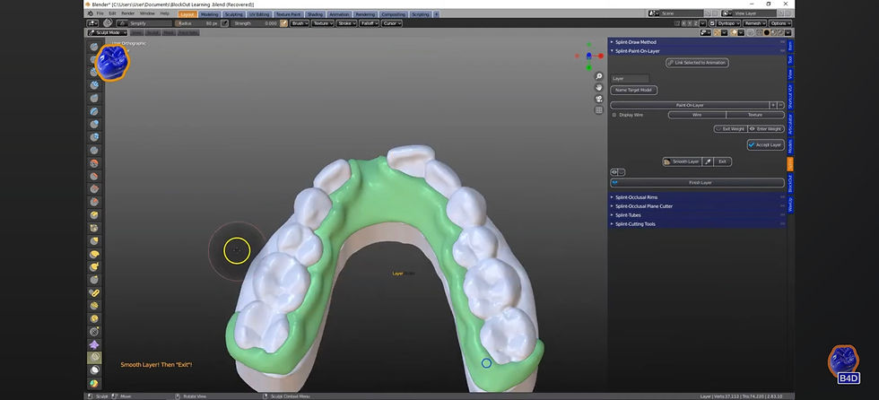
This is the geometry that goes to the printer, and it is now uniform, watertight, and predictable.
It is worth pausing here. What looks like a few clicks — paint, smooth, remesh — is actually the moment a hand-painted intention becomes manufacturing-grade geometry. Nothing automated happened in between. The designer decided the coverage, the thickness, and the resolution, and the software executed those decisions faithfully. That is the difference between a thinking tool and a black box.
"A flipper is not a small design. It is a full removable appliance compressed into one tooth."

Step 4 — Assembly: Let the Data Cut the Fitting Surface
The final stage is where preparation pays its dividend. The designer first cleans the scene with Object Management, deleting auxiliary models and hiding the completed base so that only what matters remains visible.
Then comes the optional aesthetic choice: using the sculpting tools to remove the pink gum tissue between the teeth, producing a base with no artificial gingiva showing between pontic and abutments. A matter of taste — but one the designer chooses consciously rather than inheriting from a template.
The critical technical moment follows: cutting the fitting surface. With the objects correctly named — "Layer" and "Target Model" — the Splint module's cutting tools slice the base against the finished blockout model. The tool panel offers vertex, curve, and square cutting modes, with keep-inside and keep-outside control — but the principle is always the same:

The result is a fitting surface that reproduces the surveyed, blockout-adjusted geometry exactly. No manual carving. No estimating. The analysis done in Step 2 is now physically present in the appliance that will touch the patient's tissue.
When the base is placed against the arch, the two surfaces meet as one — the base seated cleanly on the blockout model it was cut from:
Finally, the extracted tooth from Step 1 — prepared with the same cut earlier — is integrated into the base. The tooth and the base share the same surgical logic: both were defined by the same gum line, the same cervical plane. They fit because they were born from the same boundary. A quick pink color is applied to the base, the objects are unlocked — "Your object is unlocked!!" — and the completed flipper is moved off the model for inspection.

From scan to printable appliance in roughly seven minutes — because every minute of analysis was spent once, at the right stage, in the right order.
The Pro Tips, Collected
The tutorial is generous with warnings that would otherwise be learned the hard way. They are worth keeping in one place.
Stage | Tip from the tutorial | The consequence of ignoring it |
Wax Up | Keep the cervical contact line clean; avoid lines that double back on themselves | Corrupted socket geometry that breaks downstream |
Blockout | Never accept auto-default models on deep undercuts; lower the threshold (e.g., -0.4 → -0.25mm) | Appliance too tight to seat or remove |
Blockout | Sculpt extra blockout into the contact areas | Chairside grinding to fix an interference |
Splint | Hold the minus (-) key to erase over-painting; leave no unpainted holes | Holes or irregularities in the final base |
Splint | Toggle thickness visibility off to read the painted edges | Unexpectedly bulky appliance |
Splint | Always smooth the layer before the voxel remesh at 0.3mm | Poor-quality geometry unsuitable for printing |
Assembly | Name objects correctly ("Layer" and "Target Model") before cutting | Cutting tools target the wrong objects |
Why This Case Teaches More Than Its Size Suggests
It is tempting to read this tutorial as simply "how to make a flipper." But look at what the seven minutes actually contain: boundary definition, extraction planning, surveying, path-of-insertion analysis, undercut threshold judgment, blockout sculpting, layer design, thickness management, smoothing, re-meshing, and fitting-surface cutting. That is the complete vocabulary of removable appliance design, taught by the smallest case that contains all of it.
And the lessons transfer upward. The undercut logic you apply here is the same logic a full-arch removable prosthesis demands — only with more teeth to survey and more consequences for getting it wrong. The fitting-surface cut against the blockout model is the same principle behind any splint, guard, or overlay design. A designer who has truly understood the flipper has already understood the discipline; the larger cases add teeth, not thinking.
There is also a quieter argument here about what B4D was built for. Notice that at no point did the software suggest a design, auto-generate a blockout, or default its way to a finished model. Every critical value — the insertion path, the undercut threshold, the base coverage, the layer thickness, the remesh density — passed through a human decision first. This is human-led digital dentistry in its most literal form: the software is the instrument, and you are the musician.
B4D continues to invest in intelligent tools — its own segmentation capabilities, including Airways, represent serious investment in AI coding — but always on the same principle: AI that informs the designer's judgment rather than replacing it. The flipper tutorial is a perfect illustration of that balance working as intended.
Ready to Design Your Own Flipper?
The flipper is an ideal first removable case precisely because its small size makes every decision visible. If you have been postponing your first partial, there is no better entry point — and no better tool to learn it on.
Explore the modules that make this workflow possible:
• Wax Up Module — Gum line definition, extraction socket design, and tooth sectioning.
• Blockout Module — Model surveying, path-of-insertion analysis, and undercut control.
• Splint Module — Appliance layer painting, fitting-surface cutting, and smooth layer finishing.
All B4D modules are yours for life — buy once, own forever. No subscriptions, no recurring fees, no vendor lock-in. You learn once, and the skill stays with you.
Want to watch the full tutorial as it unfolds? See every click in context: One Tooth Partial — "Flipper" Design Tutorial
Your Turn: Share Your Flipper
Have you designed a partial in BlenderforDental? The B4D community lives and grows through shared cases. Post your flipper, your first splint, or your hardest blockout challenge and tag us — the best work is always the honest work.
Inspired to go further? If you would like your case or your journey featured on the B4D blog, reach out at marketing@blenderfordental.com.
Editor's Credit
This article was edited and curated by Dr. Samira Alrefaey, Blog Editor & Marketing Specialist at BlenderforDental. Through this technical exploration, we continue our mission to empower clinicians and designers with the thinking tools necessary to redefine what is possible in digital dentistry — one case, one breakthrough, one precise measurement at a time.
About BlenderforDental
BlenderforDental (B4D) is the leading platform for human-led digital dentistry, giving clinicians, designers, and labs complete control over their digital workflows — from removable appliances and full-arch prostheses to sleep and airway segmentation. B4D empowers professionals to design what patients need, not what software dictates. Buy once, own for life. Learn more at blenderfordental.com.


Comments